Abstract
The selection of an appropriate electric hoist and trolley system represents a foundational decision in industrial material handling, with direct implications for operational efficiency, workplace safety, and economic viability. This document examines the multifaceted process of choosing such equipment, moving beyond mere technical specifications to a more holistic framework. It posits that a judicious choice arises not from a single criterion, but from a structured, seven-step analysis that synthesizes load characteristics, environmental conditions, duty cycle requirements, mechanical configurations, power systems, structural integration, and long-term safety protocols. By systematically evaluating these interconnected domains, an organization can procure an electric hoist and trolley solution that is not only fit for its immediate purpose but also contributes to the sustained flourishing of the enterprise. This approach, grounded in engineering principles and safety ethics, aims to equip decision-makers in diverse global markets with the rational tools necessary for a prudent and enduring investment in their lifting infrastructure.
Key Takeaways
- Determine the precise weight, dimensions, and center of gravity for all loads.
- Analyze the operational environment for hazards like moisture, dust, or explosive atmospheres.
- Calculate the required duty cycle and lifting speed to match production demands.
- Select the optimal electric hoist and trolley based on load and application needs.
- Verify power supply compatibility and choose appropriate control systems for safety.
- Ensure the support structure can safely bear the full weight of the system.
- Establish a rigorous maintenance schedule compliant with international safety standards.
Table of Contents
- Step 1: A Foundational Inquiry into Load Characteristics and Capacity
- Step 2: Scrutinizing the Operational Environment for a Harmonious Fit
- Step 3: Defining the Rhythm of Work: Duty Cycle and Lifting Speed
- Step 4: The Mechanical Heart: Selecting the Hoist and Trolley Configuration
- Step 5: The Lifeblood of the Machine: Power Supply and Control Systems
- Step 6: The Symbiotic Relationship: Integration with Support Structures
- Step 7: A Covenant with the Future: Maintenance, Safety, and Compliance
- Frequently Asked Questions (FAQ)
- Conclusion
- References
Step 1: A Foundational Inquiry into Load Characteristics and Capacity
The journey toward selecting the correct electric hoist and trolley begins not with the machine itself, but with a profound understanding of the object to be lifted. To treat the load as a mere number—a simple declaration of mass—is to invite peril. A load possesses a character, a physical presence that demands respect and careful examination. Its weight, its shape, its very balance are the fundamental truths upon which all subsequent decisions must be built. Neglecting this initial step is akin to building a house without surveying the land; the foundation will be unstable, and the entire structure will be at risk.
Determining the Absolute Maximum Load Weight
The first question must always be: what is the heaviest object this system will ever be asked to lift? The answer cannot be an approximation or a casual estimate. Hope is not a sound engineering principle. One must seek out the precise, verified weight of the maximum load. This information is often found in manufacturer specifications, shipping manifests, or engineering diagrams. In situations where such documentation is absent, the responsible course of action is to use a calibrated industrial scale or a load cell (dynamometer) to ascertain the truth.
Once the maximum weight is known, a principle of prudence must be applied. It is a common and wise practice to select an electric hoist with a rated capacity that exceeds the maximum load weight by a margin, often around 20-25%. Why is this buffer necessary? It is not a sign of weakness in the equipment but a recognition of the imperfections of the real world. A load might be slightly heavier than documented. A lift might not be perfectly vertical, introducing side-loading forces. This margin of safety is a rational acknowledgment of unforeseen variables, a small investment in resilience that pays immeasurable dividends in preventing catastrophic failure. An electric hoist and trolley rated for 2 tons that is only ever used to lift 1.5 tons will operate with less strain, experience less wear on its components, and ultimately enjoy a longer, more reliable service life.
Understanding the Load's Physical Dimensions and Shape
Weight alone does not tell the whole story. A 1-ton block of steel presents a very different challenge from a 1-ton bundle of long pipes or a 1-ton piece of irregularly shaped machinery. The dimensions of the load—its length, width, and height—dictate the type of rigging required, the clearance needed for the lift, and the potential for the load to swing or rotate.
Consider a long, flexible load. Lifting it from a single point in the center is a recipe for disaster. The ends would droop, the load could buckle, and control would be lost. Such an object requires a spreader beam and multiple lifting points, which in turn means the electric hoist and trolley system must be able to accommodate this more complex rigging. An awkwardly shaped object, like a large motor with an off-center mounting point, presents a different sort of puzzle. Its physical form resists a simple, balanced lift. One must think in three dimensions, visualizing the path the load will take from its starting point to its destination, accounting for any obstacles or tight corners. The physical volume of the load is as consequential as its mass.
The Principle of Center of Gravity in Lifting
At the heart of a stable lift lies the concept of the center of gravity. Every object has a balance point, a theoretical spot where its entire weight can be considered to be concentrated. For a successful vertical lift, the hook of the electric hoist must be positioned directly above this center of gravity. When this alignment is achieved, the load will ascend straight up, without tilting or tumbling.
If the lifting point is offset from the center of gravity, the load will immediately tilt as soon as it leaves the ground, attempting to move its center of gravity directly under the hook. This sudden shift can be violent and unpredictable. It can cause the load to swing, striking nearby personnel or equipment. It can place immense strain on the rigging and the hoist itself. Finding the center of gravity is therefore not an academic exercise; it is a vital safety procedure. For symmetrical objects, it is often in the geometric center. For asymmetrical objects, it can be much more difficult to locate and may require calculations, manufacturer diagrams, or careful test lifts of just a few centimeters off the ground to observe the object's tendency to tilt. A profound respect for the physics of balance is a hallmark of a professional and safe lifting operation.
Step 2: Scrutinizing the Operational Environment for a Harmonious Fit
An electric hoist and trolley does not exist in a vacuum. It is a machine destined to work within a specific context, a physical space with its own character, challenges, and risks. To choose a hoist without a deep appreciation for its intended home is to ignore the powerful influence of the environment on a machine's performance, longevity, and safety. The air it breathes, the temperature it endures, the space it occupies—these are not trivial details. They are active agents that will interact with the equipment every moment of its operational life. A truly suitable electric hoist and trolley is one that is in harmony with its surroundings.
Analyzing Indoor versus Outdoor Applications
The distinction between an indoor and an outdoor application is one of the most fundamental in hoist selection. An indoor environment, such as a climate-controlled factory or warehouse, is generally a benign setting. The equipment is shielded from rain, snow, sun, and extreme temperature fluctuations. However, even an indoor space can have its own challenges, such as high levels of dust from manufacturing processes or airborne particulates in a foundry.
An outdoor environment presents a far more aggressive set of challenges. The electric hoist and trolley will be subjected to the full force of the weather. Rain and humidity promote rust and can compromise electrical components. Direct sunlight can degrade plastic components and cause the motor to overheat. Extreme cold can make lubricants viscous and metals brittle. Therefore, an outdoor-rated hoist is a different breed of machine. It will feature superior sealing, typically indicated by an Ingress Protection (IP) rating. An IP rating, like IP65, tells you precisely how well the hoist's enclosure protects against solid particles (the first digit) and liquids (the second digit). An outdoor hoist will also have corrosion-resistant finishes, such as specialized paint or galvanization, and its motor may require a "space heater" to prevent condensation from forming inside when it is not in use.
Evaluating Hazardous or Special Conditions
Some environments go beyond simply being indoors or outdoors; they are classified as hazardous. These are locations where the atmosphere itself contains substances that pose a risk of fire or explosion. A grain silo filled with combustible dust, a petrochemical plant with flammable vapors, or a paint booth with solvent fumes are all examples of hazardous locations.
In such places, a standard electric hoist and trolley is a dangerous liability. The normal operation of its motor, brakes, and electrical switches can create sparks or high temperatures that could ignite the surrounding atmosphere, leading to a catastrophic explosion. For these applications, one must select an explosion-proof hoist. These are highly specialized machines built to exacting standards. Their electrical components are housed in robust enclosures designed to contain any internal explosion, preventing it from igniting the outside air. They use spark-resistant materials, such as bronze hooks or wheels, and have specific thermal limitations to ensure their surfaces never get hot enough to become an ignition source. Choosing an explosion-proof electric hoist and trolley is not a matter of preference; it is a non-negotiable legal and ethical obligation in any hazardous environment. Other special conditions, like clean rooms in pharmaceutical or electronics manufacturing, require hoists with stainless steel components and special lubricants to prevent contamination.
Considering Space Constraints: Headroom and Footprint
The physical space available for the lifting operation is a powerful constraint. The most important spatial consideration is headroom. Headroom is the vertical distance from the point where the hoist is mounted down to the saddle of the load hook when it is at its highest possible position. Put simply, it is the amount of vertical space the hoist and trolley unit itself occupies.
In facilities with low ceilings, every centimeter of lifting height is precious. A standard electric hoist and trolley might consume too much vertical space, limiting how high a load can be lifted. In these cases, a low-headroom or ultra-low-headroom model is the necessary solution. These hoists are designed with a clever configuration, often offsetting the hoist body to one side of the beam, allowing the hook to rise up much closer to the underside of the support beam. This can add significant usable lifting height, making operations possible in spaces that would otherwise be impractical. The footprint of the entire system, including the span of the crane bridge and the travel path of the trolley, must also be mapped out to ensure it does not conflict with columns, machinery, or other structural elements of the building.
Step 3: Defining the Rhythm of Work: Duty Cycle and Lifting Speed
Every workplace has a certain rhythm, a tempo of activity that defines its productivity. An electric hoist and trolley must be chosen to match this rhythm. A hoist that is under-specified for its task will be like a runner trying to sprint a marathon; it will exhaust itself quickly, leading to premature failure and costly downtime. Conversely, a hoist that is vastly over-specified is an inefficient use of capital, a powerful engine used for a task that requires only modest strength. The concepts of duty cycle and lifting speed are the tools we use to quantify this operational rhythm, allowing us to make a rational choice that balances performance, longevity, and cost.
The Concept of Duty Cycle (FEM/ISO Classifications)
What does it mean for a hoist to be "used"? A hoist that lifts its maximum rated load once a day is used very differently from a hoist that lifts 50% of its capacity 30 times an hour, all day long. The duty cycle is a standardized classification system that captures this intensity of use. It is the most robust measure of how much work a hoist is designed to perform over its lifetime.
The two most common international standards for classifying hoist duty are from the Fédération Européenne de la Manutention (FEM) and the International Organization for Standardization (ISO). These systems consider three main factors:
- Load Spectrum: How often is the hoist lifting light, medium, heavy, or maximum loads? A hoist that consistently lifts near its capacity is under greater strain than one that mostly lifts light loads.
- Average Daily Operating Time: How many hours per day is the hoist in motion?
- Starts per Hour: How many times is the motor started and stopped within an hour? Each start-up places a thermal and mechanical stress on the motor and drive train.
These factors are combined to assign the hoist a classification, such as FEM 2m or ISO M5. A higher classification (e.g., FEM 4m) indicates a hoist designed for more severe, continuous use, with more robust gears, bearings, and motor. Selecting an electric hoist and trolley with the correct duty cycle classification is perhaps the single most important decision for ensuring a long service life and avoiding unexpected failures (Konecranes, 2026).
| FEM/ISO Class | Typical Application Description | Example Usage |
|---|---|---|
| FEM 1Bm / ISO M3 | Light Duty / Infrequent Use | Small maintenance workshops, infrequent assembly tasks. |
| FEM 2m / ISO M5 | General Purpose / Medium Duty | General manufacturing, assembly lines with moderate use. |
| FEM 3m / ISO M6 | Heavy Duty / High Volume | High-production assembly lines, steel fabrication shops. |
| FEM 4m / ISO M7 | Severe Duty / Continuous Use | Foundries, steel mills, automated processes with near-constant operation. |
Matching Hoist Speed to Production Needs
The speed at which the hoist lifts and lowers the load is a direct factor in the productivity of the workstation. A speed that is too slow can create bottlenecks, leaving workers waiting and slowing down the entire production line. A speed that is too fast can make it difficult to position loads precisely and can increase the risk of accidents if the operator is not highly skilled.
The ideal lifting speed is a balance between efficiency and control. For applications requiring the movement of loads over long vertical distances, a faster speed is generally desirable to minimize transit time. For applications that involve precise placement, such as positioning a delicate mold into a press or assembling complex machinery, a slower, more controllable speed is paramount. The choice is not simply between "fast" and "slow." Many modern hoists offer solutions that provide the best of both worlds.
Single-Speed, Two-Speed, or Variable Frequency Drive (VFD)?
The control over the lifting speed is a key feature that distinguishes different models of electric hoist.
- Single-Speed Hoists: These are the most basic and economical option. The motor runs at one constant speed. They are suitable for simple, repetitive tasks where precision is not the primary concern.
- Two-Speed Hoists: These hoists have a motor with two distinct windings, allowing for a main, fast speed and a secondary, slow speed (often at a ratio of 4:1 or 6:1). The operator can use the fast speed for long travel and then switch to the slow speed for the final, precise positioning of the load. This offers a significant improvement in control over single-speed models.
- Variable Frequency Drive (VFD) Hoists: A VFD (also known as an inverter) is a sophisticated electronic controller that adjusts the frequency of the electrical power supplied to the motor. By doing so, it can provide smooth, stepless acceleration and deceleration, and allow the operator to vary the speed across the entire range, from a slow creep to full speed. VFDs offer the ultimate in load control. The "soft starts" reduce mechanical shock on the hoist and the support structure, extending the life of the components. The precise control minimizes load swing and allows for exact placement, improving both safety and efficiency. While the initial investment for a VFD-equipped electric hoist and trolley is higher, the benefits in terms of reduced wear, enhanced safety, and greater productivity often provide a rapid return on that investment.
Step 4: The Mechanical Heart: Selecting the Hoist and Trolley Configuration
Having understood the load, the environment, and the rhythm of work, we can now turn our attention to the machine itself. The mechanical configuration of the electric hoist and trolley is its very essence, defining how it generates lifting force and how it moves through space. The choices made here—between chain and wire rope, between different trolley propulsion methods, between various suspension types—are not arbitrary. Each configuration has its own set of virtues and limitations, its own suitability for different tasks. A thoughtful selection requires a comparative analysis, a weighing of trade-offs to find the optimal mechanical heart for your specific application.
Chain Hoist versus Wire Rope Hoist: A Comparative Analysis
The lifting medium—the flexible element that connects the hook to the hoist body—is the most fundamental distinction. The two dominant technologies are chain and wire rope.
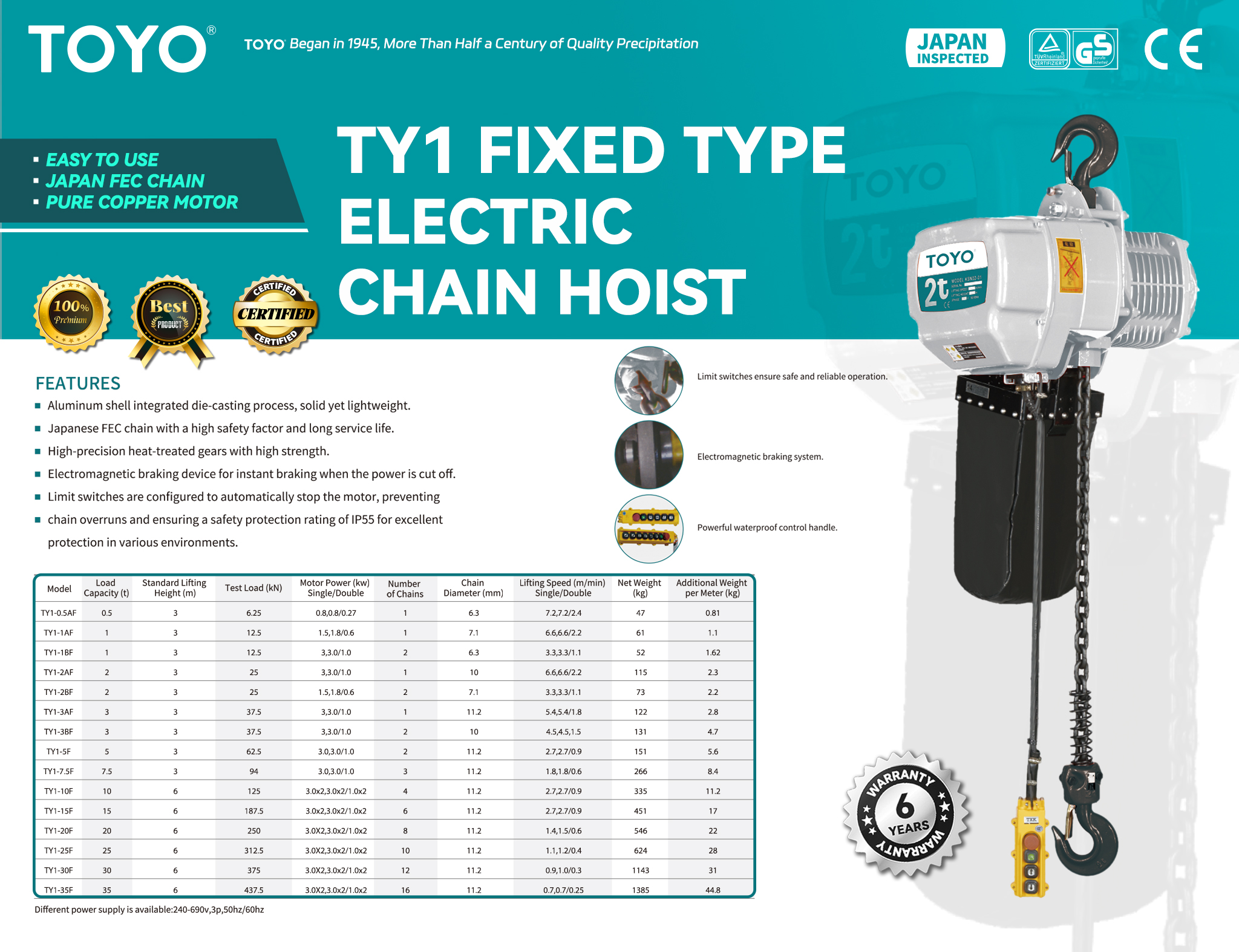
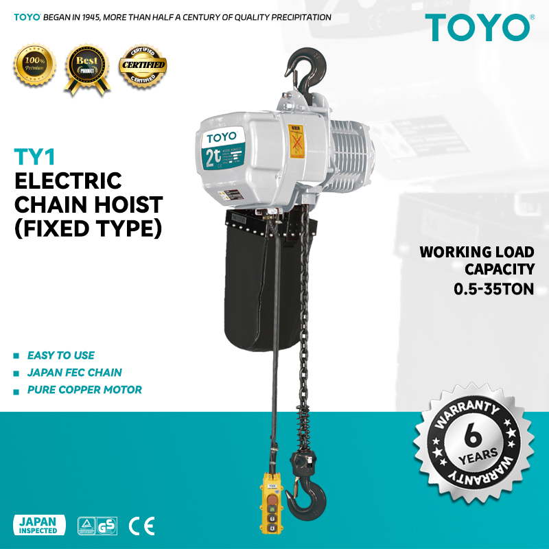
An electric chain hoist uses a hardened, calibrated steel load chain that runs over a pocketed liftwheel. They are generally more compact, offer better durability in harsh environments, and are more tolerant of lifting angles that are not perfectly vertical (though true vertical lifting is always the ideal). The chain is a robust element, less susceptible to damage from crushing or abrasion than wire rope. Maintenance is also often simpler. For these reasons, versatile electric chain hoists are extremely popular in a vast range of applications, from small workshops to demanding industrial production lines, typically in capacities up to about 25 tons (Demag, 2026).
An electric wire rope hoist uses a steel cable wound around a grooved drum. Wire rope hoists excel in applications requiring very high lifting heights, faster lifting speeds, and extremely heavy capacities (often reaching 100 tons or more). They provide a very smooth, true vertical lift without the slight "polygon effect" of a chain, which can be important for very sensitive loads. However, the wire rope is more susceptible to wear and damage from improper handling, and the larger drum mechanism means the hoist itself is generally larger and more expensive than a chain hoist of a similar capacity.
| Feature | Electric Chain Hoist | Electric Wire Rope Hoist |
|---|---|---|
| Typical Capacity | 0.25 to 25 tons | 2 to 100+ tons |
| Lifting Medium | Hardened steel load chain | Steel wire rope |
| Durability | High; resistant to abrasion and harsh environments. | Moderate; susceptible to crushing, kinking, and abrasion. |
| Lift Type | True vertical lift is possible but less inherent. | Inherently true vertical lift (no hook drift on most models). |
| Headroom | Generally more compact, better for low headroom. | Larger, requires more headroom due to drum size. |
| Lifting Speed | Generally slower. | Generally faster speeds are available. |
| Cost | More economical, especially at lower capacities. | Higher initial cost. |
| Common Use | Workshops, assembly lines, jib cranes, general purpose. | Heavy manufacturing, long lifts, high-speed production. |
Trolley Types: Manual, Motorized, and Geared
The trolley is the wheeled carriage that allows the hoist to move horizontally along the support beam or crane bridge. The method of propulsion for the trolley is a key choice.
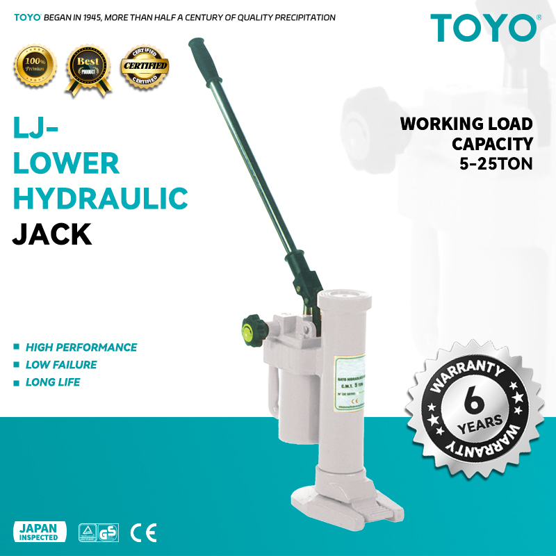
- Manual Trolley (Push Trolley): This is the simplest and most economical option. The operator moves the trolley by pushing or pulling on the load itself. This is only suitable for lighter loads (typically under 2 tons), short travel distances, and infrequent use. The effort required can be significant, and precise positioning can be difficult.
- Geared Trolley (Hand-Geared Trolley): A geared trolley is also manually operated, but it includes a hand chain that hangs down to the operator. Pulling this chain turns a set of gears that drive the trolley wheels. This provides a mechanical advantage, making it much easier to move heavier loads than with a push trolley. It also allows for more precise positioning. Geared trolleys are a good intermediate solution for applications where a motorized trolley is not necessary but pushing the load is impractical.
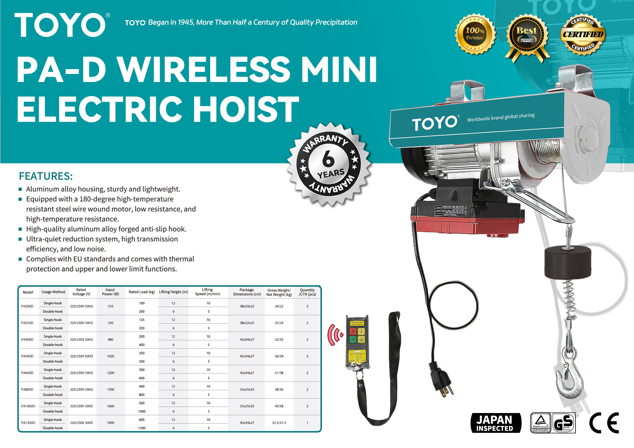
- Motorized Trolley (Electric Trolley): This trolley has its own electric motor, controlled by the same pendant or remote as the hoist. It provides effortless horizontal movement at the push of a button. Motorized trolleys are the standard for heavy loads, long travel distances, and frequent use. Like hoist motors, they can be single-speed, two-speed, or equipped with a VFD for smooth, controlled travel. A motorized electric hoist and trolley system provides the highest level of efficiency, safety, and ergonomic benefit for the operator.
Suspension Methods: Hook, Lug, and Trolley Mounting
How the hoist body is attached to the overhead support is another critical detail.
- Hook Suspension: The hoist has a top hook that can be hung from a fixed anchor point, a beam clamp, or a trolley. This is a versatile and portable solution, allowing the hoist to be easily moved between different locations. It is common for smaller capacity hoists used in maintenance or temporary setups.
- Lug Suspension: Instead of a hook, the hoist has a fixed mounting lug or bracket that is bolted directly to a trolley. This provides a more rigid and permanent connection, reducing the overall headroom compared to a hook-suspended hoist on a trolley. It is a common configuration for hoists that are permanently installed on a crane system.
- Integral Trolley: In this configuration, the hoist and trolley are designed and built as a single, inseparable unit. This is the most common design for most motorized electric hoist and trolley systems. It offers the most compact design and the best possible headroom, as the components are optimized to work together.
The choice of suspension depends on the need for portability versus the desire for a permanent, low-headroom installation.
Step 5: The Lifeblood of the Machine: Power Supply and Control Systems
An electric hoist and trolley is an electromechanical system. Its muscles are mechanical, but its nervous system and lifeblood are electrical. The proper specification of the power and control systems is as vital to its function as the gears and chains. A mismatch in power supply can damage the motor or prevent it from working at all. A poorly chosen control system can compromise safety and precision. Therefore, a careful examination of the electrical infrastructure and the human-machine interface is an indispensable part of the selection process.
Matching Voltage, Phase, and Frequency
Electricity is not a one-size-fits-all commodity. The electrical power available at the installation site must precisely match the requirements of the hoist's motor. There are three key parameters to verify:
- Voltage: This is the electrical potential difference. Common industrial voltages include 230V, 380V, 400V, 415V, 460V, or 575V. Supplying a motor with the wrong voltage is a near-certain way to destroy it. A motor designed for 460V will quickly burn out if connected to a 230V supply and vice-versa.
- Phase: Most industrial motors, including those in an electric hoist and trolley, operate on three-phase power. It provides a smoother, more efficient delivery of power compared to the single-phase power found in residential outlets. Attempting to run a three-phase motor on a single-phase supply will not work without a special converter and is generally not recommended.
- Frequency: Measured in Hertz (Hz), this is the rate at which the alternating current cycles. The two global standards are 60 Hz (prevalent in North America and parts of South America) and 50 Hz (prevalent in Europe, Asia, Africa, and the Middle East). A motor designed for one frequency will not operate at its correct speed and power on the other, and it may overheat.
Before purchasing any electric hoist, it is an absolute necessity to confirm the available voltage, phase, and frequency at the point of installation and ensure the chosen model is compatible. Many manufacturers offer hoists that are "dual voltage" or can be easily reconfigured for different power supplies, but this must be specified at the time of order.
Pendant versus Remote Control: Ergonomics and Safety
The control system is the interface through which the human operator communicates their intentions to the machine. The two primary options are a pendant control and a radio remote control.
- Pendant Control: This is a handheld control station that is connected to the hoist by a flexible electrical cable. The operator walks along with the hoist and load, operating the push-buttons for up/down lift and horizontal travel. Pendants are reliable, economical, and do not require batteries. However, the cable can be a potential snagging hazard, and it forces the operator to remain in close proximity to the load. The length of the pendant cable must be carefully considered; it should be long enough to allow the operator to stand at a safe distance from the load but not so long that it drags on the floor.
- Radio Remote Control: A remote control system uses a wireless transmitter (handheld by the operator) and a receiver (mounted on the hoist). This untethers the operator from the machine, offering significant advantages in both safety and ergonomics. The operator can choose the safest possible vantage point from which to view the lift, away from the suspended load and any potential pinch points. It eliminates the snagging hazard of a pendant cable and can reduce operator fatigue. While the initial cost is higher and they require batteries, the safety and flexibility benefits make radio remote controls an increasingly popular choice, especially for larger crane systems or in complex environments.
Understanding Safety Features: Limit Switches, Brakes, and Overload Protection
A modern electric hoist and trolley is equipped with a suite of safety features designed to protect the equipment, the load, and, most importantly, the personnel. Understanding these features is not just for technicians; it is for anyone responsible for specifying or purchasing the equipment.
- Limit Switches: These are small switches that automatically cut power to the motor when a certain travel limit is reached. An upper limit switch prevents the hook block from crashing into the hoist body ("two-blocking"), which could break the chain or wire rope. A lower limit switch prevents the chain or rope from being run completely out of the hoist. Geared limit switches can also be used to define slow-down zones and final stop points for both hoisting and trolley travel.
- Brake System: The brake is arguably the most important safety component. It is what holds the load securely when the motor is not running. Most modern electric hoists use a fail-safe electromagnetic disc brake. When power is applied to the motor, an electromagnet disengages the brake. When power is cut (either intentionally or due to a power failure), springs immediately engage the brake, securely holding the load. The brake must be powerful enough to stop and hold more than the rated capacity of the hoist.
- Overload Protection: This feature is designed to prevent the operator from lifting a load that exceeds the hoist's rated capacity. The most common type is a slipping clutch. It is a mechanical device located in the drive train. If the load is too heavy, the clutch will slip, preventing the hoist from lifting while the motor continues to turn. This provides a clear signal to the operator that the load is too heavy, without causing damage to the motor or gears. Some hoists may use electronic overload devices that monitor the motor's current draw and cut power if it exceeds a preset limit. An overload device is a vital safeguard against human error and unknown load weights. It is a feature that should be considered standard on any modern, high-quality industrial electric chain hoist.
Step 6: The Symbiotic Relationship: Integration with Support Structures
An electric hoist and trolley does not float in mid-air. It is part of a larger system, and its performance is entirely dependent on the structure that supports it. This relationship is symbiotic; the hoist relies on the structure for its stability and path of movement, while the structure must be robust enough to bear the dynamic loads imposed by the hoist. The process of integration involves ensuring mechanical compatibility, verifying structural integrity, and understanding the mechanisms that connect the two. To neglect this phase is to risk a failure not of the hoist, but of the very foundation it rests upon.
Compatibility with I-Beams, Jib Cranes, and Gantry Systems
The electric hoist and trolley is most often designed to run along the flange of a steel beam. The most common type is an I-beam, but they are also used on monorails, the bridge of an overhead crane, or the boom of a jib crane.
- I-Beams and Monorails: When the trolley runs on a single, fixed beam, it's known as a monorail system. It is crucial that the trolley's wheels are compatible with the shape and width of the beam's flange. Beams can have flat or tapered flanges, and the trolley must be specified or adjusted accordingly. The width of the flange is also a critical dimension; the trolley must be adjustable to fit it snugly, without being too tight (which would cause binding) or too loose (which would allow for excessive side-to-side play).
- Overhead Cranes: In an overhead or gantry crane system, the hoist and trolley run along a moving bridge that spans the width of the work bay. Here, the hoist is part of a three-axis system (vertical, horizontal along the bridge, and horizontal along the runways). The integration involves ensuring the trolley is compatible with the bridge beam and that the crane's overall capacity is sufficient for the hoist and its intended load.
- Jib Cranes: A jib crane consists of a hoist and trolley running along a horizontal boom that is mounted to a wall or a floor-standing pillar. This provides circular or semi-circular coverage in a specific work area. The compatibility check involves matching the trolley to the jib boom and ensuring the total weight of the hoist, trolley, and load does not exceed the capacity of the jib crane itself.
Structural Integrity and Load Bearing Calculations
This is a domain where assumptions are forbidden. The support structure—be it a simple beam or a complex crane system—must be capable of safely supporting not just the static weight of the electric hoist and trolley plus its maximum rated load, but also the dynamic forces generated during operation.
When a hoist starts and stops, it creates inertial forces. When a load is lifted, there are impact factors. These dynamic loads can be significantly higher than the simple static weight. A qualified structural engineer must perform calculations to verify that the beam or crane structure can handle these forces without excessive deflection (bending) or, in the worst case, catastrophic failure. The engineer will consider the beam size, its material properties, its span between supports, and the specific characteristics of the hoist being installed. They will also verify that the building structure itself (the columns or ceiling joists supporting the crane) is adequate. A formal structural analysis and certification are not optional steps; they are a fundamental requirement for a safe lifting system (ASME, 2020).
The Role of Beam Clamps and Trolley Adjustments
The physical connection between the trolley and the beam is of paramount importance.
- Trolley Adjustment: Most quality trolleys are designed to be adjustable to fit a range of beam flange widths. This adjustment is typically achieved by rearranging spacing washers on a threaded suspension pin. It is vital that this adjustment is performed correctly according to the manufacturer's instructions. An improperly adjusted trolley can lead to uneven wheel wear, binding, or even the trolley de-railing from the beam.
- Beam Clamps: For semi-permanent or temporary mounting of a hoist to a beam, a beam clamp can be used. This device clamps securely onto the beam flange and provides a robust anchor point for a hook-suspended hoist. Like the hoist itself, a beam clamp has a rated capacity that must never be exceeded. It must be installed correctly on the beam's center-line to ensure a vertical pull.
- Safety Lugs: Most motorized and geared trolleys are equipped with safety lugs, also known as drop stops. These are metal plates that extend below the beam flange on either side of the trolley. In the highly unlikely event of a wheel or axle failure that could cause the trolley to tip, these lugs would catch on the beam flange, preventing the trolley and its load from falling. They are a simple but vital last-line-of-defense safety feature.
The integration of the electric hoist and trolley with its support structure is a critical juncture where mechanical and civil engineering principles converge. It demands a meticulous attention to detail, from the fit of the wheels on the flange to the certified capacity of the building's steel.
Step 7: A Covenant with the Future: Maintenance, Safety, and Compliance
Purchasing an electric hoist and trolley is not the end of a process, but the beginning of a long-term relationship. It is an entry into a covenant of responsibility—a promise to maintain the equipment, to operate it safely, and to comply with the standards that govern its use. This final step in the selection process involves looking ahead and planning for the entire lifecycle of the equipment. A hoist that is purchased without a plan for its upkeep and safe use is a depreciating asset and a potential liability. A hoist that is integrated into a comprehensive program of maintenance and safety is a productive tool that contributes to the well-being of the organization for years to come.
Adherence to International Standards (ASME, ISO, OSHA)
The world of lifting equipment is governed by a robust framework of safety standards developed by national and international bodies. These standards are not arbitrary rules; they are the accumulated wisdom of decades of engineering experience and accident analysis. They represent a collective commitment to preventing injury and ensuring reliability.
Key standards include:
- ASME B30.16: An American National Standard that provides safety requirements for overhead hoists. It covers design, installation, inspection, testing, maintenance, and operation.
- ISO Standards: The International Organization for Standardization has numerous standards related to cranes and hoists, which are widely adopted globally.
- OSHA Regulations: In the United States, the Occupational Safety and Health Administration (OSHA) sets legally enforceable standards for workplace safety, including detailed regulations for overhead and gantry cranes (OSHA 1910.179).
When selecting an electric hoist and trolley, one should ensure that it is designed and manufactured in compliance with the relevant standards for your region. Reputable manufacturers will clearly state which standards their products meet. Compliance is not just about avoiding fines; it is about ensuring you are purchasing a machine that has been built to a proven level of safety and quality (Lift-All, 2025).
Developing a Proactive Maintenance Schedule
An electric hoist is a machine with moving parts that are subject to wear. A proactive maintenance program is essential to catch and correct this wear before it leads to a failure. A comprehensive program, as outlined by standards like ASME B30.16, typically includes several levels of inspection:
- Pre-Shift Inspection: A visual and functional check performed by the operator before each shift. This includes checking the controls, hooks, latches, and chain/wire rope for any obvious damage.
- Frequent Inspection: A more detailed visual inspection performed monthly (or more often in severe service). This involves checking the braking system, limit switches, and looking for signs of wear on the chain, wheels, and other components.
- Periodic Inspection: A thorough, hands-on inspection performed annually (or as recommended) by a qualified person. This involves dismantling certain components to check for internal wear, measuring the chain or rope for stretch, and load testing the hoist to verify its capacity and brake function.
A logbook must be maintained for each hoist, documenting all inspections, maintenance, and repairs. This creates an auditable record of the hoist's condition and the organization's commitment to safety.
Operator Training and Personal Protective Equipment (PPE)
The safest hoist in the world can become dangerous in the hands of an untrained operator. No person should be permitted to operate an electric hoist and trolley without receiving thorough training on its specific controls, safety features, and proper operating procedures. Training should cover pre-use inspection, safe rigging practices, understanding the hoist's capacity limits, and emergency procedures.
The operator and anyone working in the immediate vicinity of the lifting operation must also use appropriate Personal Protective Equipment (PPE). This typically includes:
- Hard Hat: To protect against falling objects or impact with the load.
- Safety Glasses: To protect the eyes from debris.
- Steel-Toed Boots: To protect the feet from crushing injuries.
- Gloves: To protect the hands during rigging.
The selection of an electric hoist and trolley is complete only when a plan for its future is in place. This plan, rooted in compliance, proactive maintenance, and operator training, is the final, essential element in ensuring that the equipment remains a safe, reliable, and productive asset for its entire service life.
Frequently Asked Questions (FAQ)
What is the primary difference between an electric chain hoist and an electric wire rope hoist? The core difference lies in the lifting medium. An electric chain hoist uses a hardened steel chain that engages with a pocketed liftwheel, making it compact, durable in harsh conditions, and generally more cost-effective for capacities up to about 25 tons. An electric wire rope hoist uses a steel cable wound onto a grooved drum, which provides a smoother, true vertical lift, faster speeds, and is preferred for very high capacities and long lifting heights.
How do I determine the correct duty cycle (FEM/ISO rating) for my application? To determine the correct duty cycle, you must analyze your lifting patterns. Consider how many hours per day the hoist will operate, how many lifts it will perform per hour (starts/stops), and the average weight of the loads relative to the hoist's maximum capacity (load spectrum). A high-production assembly line lifting heavy parts continuously will require a much higher duty cycle (e.g., FEM 3m or 4m) than a maintenance shop hoist used a few times a week (e.g., FEM 1Bm). Consulting the manufacturer's guidelines or a lifting specialist is highly recommended.
Is a remote control safer than a pendant control? Generally, a radio remote control is considered to offer a higher level of safety. It allows the operator to move freely and choose the best possible vantage point, away from the suspended load and potential hazards. A pendant control requires the operator to stay close to the load, within the range of the connecting cable, which can be a snagging risk and may place the operator in a more vulnerable position.
Can I use a standard electric hoist in an environment with explosive dust or vapors? Absolutely not. Using a standard electric hoist in a hazardous (explosive) atmosphere is extremely dangerous and prohibited by safety regulations. The normal operation of the motor, brakes, and switches can create sparks that could ignite the environment. You must use a specially designed explosion-proof hoist that is certified for the specific hazardous classification of your area.
What does the IP rating on an electric hoist signify? The IP (Ingress Protection) rating is a two-digit code that indicates the level of protection the hoist's electrical enclosure provides against the intrusion of foreign objects and moisture. The first digit (0-6) rates protection against solids (like dust), and the second digit (0-8) rates protection against liquids (like water). A higher number indicates better protection. For example, a hoist with an IP65 rating is completely dust-tight and protected against water jets from any direction, making it suitable for many outdoor or wash-down applications.
Why is professional installation and load testing important? Professional installation ensures that the electric hoist and trolley is mounted correctly, aligned properly on its support beam, and wired safely according to electrical codes. Following installation, a load test, typically performed at 125% of the rated capacity, is conducted by a qualified person. This test verifies the structural integrity of the entire system, including the hoist, trolley, support beam, and mounting points, and confirms that the brake system is functioning correctly and can safely hold the load. It is a critical final step to ensure the system is safe for use.
How often should the load chain or wire rope be replaced? The load chain or wire rope must be inspected regularly as part of the maintenance schedule. It should be replaced immediately if it shows any signs of damage, such as cracks, nicks, gouges, heat damage, or corrosion. For chain, it should also be replaced if it is stretched beyond the manufacturer's specified limit (typically measured over a set number of links). For wire rope, it should be replaced if it has a certain number of broken wires, kinking, or crushing. There is no fixed time interval for replacement; it is based entirely on the component's condition as determined by regular, thorough inspections.
Conclusion
The selection of an electric hoist and trolley is a task of significant consequence, one that extends far beyond a simple commercial transaction. It is an exercise in applied reason, requiring a methodical and holistic evaluation of interconnected factors. As we have explored through this seven-step framework, a responsible choice is not born from a single data point, but emerges from a rich understanding of the load's character, the environment's demands, the rhythm of the work, the mechanics of the machine, the nature of its power, its integration with its support, and a forward-looking commitment to its long-term care.
To ignore any of these facets is to introduce a vulnerability into the system. A decision grounded solely in capacity without considering the duty cycle courts premature failure. A choice based on price without evaluating the environmental requirements risks rapid deterioration. The path to a successful and enduring lifting solution is paved with diligence and a respect for the complexities involved. By thoughtfully navigating these seven domains, managers, engineers, and operators across the diverse industrial landscapes of South America, Russia, Southeast Asia, the Middle East, and South Africa can equip their facilities with an electric hoist and trolley system that is not merely adequate, but is a true catalyst for enhanced safety, productivity, and prosperity.
References
American Society of Mechanical Engineers. (2020). ASME B30.16-2020: Safety standard for overhead hoists (underhung). ASME.
Demag. (2026). Chain hoists. Demag Cranes & Components GmbH. Retrieved from
Holloway Houston Inc. (2023). Different types of hoists and their applications. HHI Lifting. Retrieved from
Holloway Houston Inc. (2021). Lever hoists: Functions, applications, and operating principles. HHI Lifting. Retrieved from https://www.hhilifting.com/en/news/post/what-is-a-lever-hoist-and-how-it-works-a-short-guide-on-lever-hoists
Konecranes. (2026). Electric chain hoists. Konecranes. Retrieved from
Konecranes. (2026). Electric chain hoists. Konecranes Saudi Arabia. Retrieved from
Lift-All. (2025). Lift-All hoists catalog. Retrieved from
Occupational Safety and Health Administration. (n.d.). 1910.179 – Overhead and gantry cranes. U.S. Department of Labor. Retrieved from
T-Lifting. (2025). How to use a chain hoist: Complete guide for beginners and professionals. Hangzhou Top Lift Industries Co., Ltd. Retrieved from https://www.t-lifting.com/How-to-Use-a-Chain-Hoist-Complete-Guide-for-Beginners-and-Professionals-id47286996.html